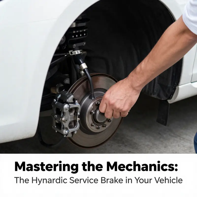
Understanding your vehicle’s service brake is crucial for safety and performance. Hydraulic brakes play a vital role in how effectively your vehicle stops. As local private car owners, used car buyers, and small business fleet operators, you benefit from knowing how these systems function and what it takes to maintain them. The following chapters delve into the intricacies of hydraulic brake operation, the systems that support its functionality, and essential maintenance practices that can enhance your vehicle’s longevity and safety.
From Pedal to Power: The Hydraulic Journey of a Vehicle’s Service Brake

When a driver presses the brake pedal, a precise chain reaction unfolds inside a vehicle’s braking system. The service brake, normally hydraulically operated, relies on a carefully choreographed transfer of force that begins with a simple foot movement and ends with the wheels shedding speed or stopping altogether. This process hinges on a fundamental property of liquids: incompressibility. Brake fluid does not compress under pressure, so the tiny movement of the pedal is translated into a rapid, uniform rise in pressure that travels through rigid metal lines and flexible hoses to every wheel. In essence, the hydraulic system acts as a force multiplier. A modest input from the driver is converted into a much larger hydraulic force at the calipers or wheel cylinders, which, in turn, clamp pads against rotors or shoes against drums. The result is controlled deceleration that, when properly tuned, feels natural and predictable to the operator. This predictability is not accidental; it is the product of decades of refinement in materials, geometries, and safety-oriented thinking about how fluid pressure can be harnessed to manage kinetic energy safely and efficiently across a wide range of operating conditions.
At the heart of modern hydraulic braking for heavy and industrial applications lies a move toward compact, integrated subsystems. In many contemporary machines, especially electric bag lifting vehicles, engineers have replaced traditional hydraulic sources with a miniature motive power unit (MPU). This MPU serves as the primary pump, generating the necessary hydraulic pressure to feed the service brake circuit. A companion component, the energy accumulator, stores pressurized fluid so that the system can sustain braking performance during peak demand or compensate for brief failures of the MPU. The accumulator provides a reserve of pressure, smoothing out transient demands and reducing the likelihood of a momentary drop in braking force during a rapid sequence of pedal applications. Together, the MPU and accumulator create a compact hydraulic backbone that supports reliable deceleration in environments where space and maintenance efficiency are critical, such as material-handling fleets and industrial settings where high throughput and safety cannot be compromised.
Despite this streamlined arrangement, the operator’s control over braking remains intuitive. The pedal pressure reduction valve plays a pivotal role in translating the user’s intent into a proportional hydraulic response. When the pedal is depressed, this valve modulates the pressure that reaches the service brakes, ensuring that the braking force increases smoothly as pedal travel increases. Instead of a binary on/off feel, the driver experiences a graded response that facilitates precise stopping power. This proportional control is essential for delicate maneuvering in tight spaces or when carrying heavy loads, where abrupt halts could destabilize a load or damage a structure. The design philosophy here is straightforward: give the operator predictable, linear feedback, so that braking becomes an extension of the driver’s body rather than a force to be fought against. The valve, therefore, is as much a mood-regulator as it is a pressure shaper, shaping the character of the brake feel and the vehicle’s response to every inch of pedal travel.
Safety and reliability are further enhanced by a network of pressure monitoring switches that keep the system honest under all circumstances. A motor starting pressure switch ensures that the hydraulic pump is up to pressure before the brakes engage, preventing a sudden, incomplete application that might occur if the pump were still priming. A motor flameout pressure switch guards against unsafe shutdowns, ensuring that if the motor fails, the system can respond in a controlled manner rather than leaving the operator stranded with insufficient braking capability. The service brake pressure switch provides an essential check that there is sufficient pressure before the brakes engage, acting as a safeguard against accidental release or partial engagement. These switches form a digital-analog hybrid safety net that complements the physical integrity of the hydraulic path. Together with the MPU and accumulator, they contribute to a system that is not only powerful but also self-checking, capable of alerting operators and maintenance personnel to anomalies before a malfunction becomes a hazard.
Protection against cascading failures is further enhanced by a cutoff valve that isolates the hydraulic circuit in the event of a fault. Isolation is not merely a defensive measure; it preserves the integrity of the remaining circuit and prevents a single point of failure from compromising the entire braking system. In practice, the cutoff valve acts as a last line of defense, maintaining controllable behavior even when a component in the feed line or a valve assembly proves unreliable. This kind of redundancy is particularly important in industrial contexts where downtime is costly and safety protocols demand multiple layers of protection.
The real-world geometry of the hydraulic system reflects a deliberate, modular approach. The oil outlet from the pedal pressure reduction valve connects to the service brake pressure switch and then to the brake cylinder via a carefully routed pipeline. The return path from the pedal valve travels through the cutoff valve back to the MPU’s oil return opening. This layout ensures that the active brake channel remains primed and ready while enabling a clean, low-friction return path. The result is a compact circuit that can be laid out with minimal cross-overs and without aggressive routing that would invite leaks or heat build-up. In heavy-duty applications, where space is at a premium and environmental conditions can be harsh, such streamlining translates into easier maintenance, quicker diagnostics, and reduced risk of damage from vibrations or thermal expansion.
One of the most compelling advantages of hydraulic braking in these modern systems is the balance it achieves between simplicity and capability. The core mechanism—pressurized fluid moving from a master-like source to brake actuators—derives its elegance from the way it relies on the rigid, incompressible nature of liquids. This means that changes in pressure propagate through the circuit with minimal delay, delivering near-instantaneous responsiveness to the operator. The system’s simplicity also supports reliability. Fewer moving parts in the primary power path, fewer potential leak points, and a design that emphasizes leak detection and secure seals all contribute to lower maintenance burdens. Yet the same simplicity can be leveraged to add sophisticated safety features when needed. ModernABS and brake assist systems do not replace hydraulic logic; they complement it by dynamically modulating pressure or augmenting braking force during emergent conditions. In a well-designed network, hydraulic pressure is the anchor, while electronic controllers provide finesse and protection against wheel lock or fatigue under heavy loads.
The integration of hydraulic braking with electric and hybrid propulsion architectures reflects a broader shift in vehicle engineering. In electric bag lifting fleets and similar industrial platforms, electro-hydraulic or hybrid systems offer a pathway to compactness, energy efficiency, and improved maintenance profiles. Electric pumps and accumulators can be orchestrated to deliver peak pressure precisely when needed, storing energy during idle periods and reusing it during brake application. In this sense, hydraulic braking becomes a smart partner to electric powertrains, not a relic of conventional vehicles. The small footprint of a miniature motor-driven pump, combined with a compact accumulator, makes it feasible to house the whole brake subsystem in tight quarters, alongside other control elements. The approach is no accident; it is the outcome of a nuanced understanding of how energy is generated, stored, and deployed within a vehicle that must operate under demanding conditions with minimal downtime.
Maintenance in this architecture emphasizes system integrity and fluid quality as much as it does mechanical wear. A rigorous maintenance routine includes regular inspection of the hydraulic lines for signs of wear, cracking, or abrasion. The brake pads or shoes must be checked for thickness, with replacement undertaken when wear approaches the manufacturer’s specified limit. This is not merely about preserving stopping power; it is about preventing damage to rotors or drums, which can escalate repair costs and downtime. Fluid health is equally critical. Brake fluid can degrade over time due to moisture absorption, temperature cycling, and contamination. Routine fluid checks and replacements—following the manufacturer’s schedule—are essential for maintaining consistent pressure transmission and to minimize the risk of a soft or sinking pedal. In addition, the system should be bled regularly to remove air, which compromises pedal feel and braking efficiency. In practice, a soft pedal often indicates air in the lines or insufficient fluid; bleeding, then rechecking, becomes a standard diagnostic step before pursuing deeper component inspections.
Another dimension of maintenance involves ensuring the hydraulic circuit operates within its prescribed pressure envelope. While the exact figures can vary by vehicle and application, a typical operating range for the service brake hydraulic circuit sits around a few hundred psi, with peak demands capable of approaching the higher end of the envelope during emergency stops. In many industrial contexts, designers target a peak pressure in the neighborhood of 2025 psi (approximately 140 bar). This broad figure must be interpreted not as a single value but as a design target that reflects the system’s size, the mass being slowed, and the safety margins expected in real-world operation. Regular pressure checks with a calibrated gauge help verify that the MPU, accumulator, and valve trains maintain this range. If the measured pressure is consistently high or low, or if the pedal feel becomes noticeably spongy, maintenance personnel should investigate, starting from the simplest explanations—air pockets, degraded seals, or leaking hoses—before moving to more complex failure modes like a failing master-like component or malfunctioning sensors.
Air ingress remains a common culprit behind a compromised braking feel. It can occur through imperfect connections, worn seals, or micro-leaks in hoses under vibration. Bleeding the system is a routine remedy and, in practice, is often performed as part of a broader diagnostic to confirm the integrity of the circuit. If the problem persists after bleeding, technicians will inspect the seals around the master cylinder and caliper pistons and verify that the line routes are free of kinks or restrictions. Worn seals or leaks in the hose network can allow microscopic air bubbles to form and persist, eroding pedal stiffness and reducing braking efficiency. The system’s design, with its multiple safety switches and the cutoff valve, helps isolate the problem area and prevent a cascading failure that could affect all wheels. In this way, the combination of hardware and procedural safeguards serves as both a brake system and a safety management framework.
The chapter’s technical narrative would be incomplete without referencing the broader ecosystem in which hydraulic braking operates. Modern systems, even when hydraulically based, typically interact with electronic control units that coordinate ABS, brake assist, and, in some cases, regenerative braking or energy recovery strategies. ABS sensors at each wheel feed real-time information to a control module that modulates hydraulic pressure to prevent wheel lock during hard braking. This electronic intervention does not replace hydraulic force; it refines it, ensuring that deceleration remains controllable on slippery surfaces and under dynamic load conditions. In hybrid or electro-hydraulic configurations, the control logic may orchestrate actuator performance with energy flux in the system, balancing braking power with energy recovery goals and overall vehicle dynamics. The result is a braking system that leverages both the reliability and immediacy of hydraulics and the precision and adaptability of electronics, creating a safety-critical interface that is robust, flexible, and increasingly connected to the vehicle’s wider control architecture.
In exploring the practical realities of maintaining and diagnosing these systems, it is important to keep a concrete picture of the physical components and their interactions. The service brake cylinders or calipers at each wheel are the final actuators that apply friction to slow the vehicle. The brake pads or shoes convert kinetic energy into heat via friction, challenging the rotor or drum with high surface pressures. The hydraulic lines and hoses must endure continuous pressure cycles, temperature variation, and potential contamination, all while maintaining a sealed, leak-free path for fluid. The pedal valve and the pedal pressure reduction valve govern the entry of hydraulic pressure into the network, while the return path through the cutoff valve provides a controlled discharge back to the MPU. The pressure switches, collectively, act as an embedded sensing and safety network, ensuring that the system can respond to abnormal conditions with appropriate safeguards. In such a context, maintenance becomes a disciplined habit: routine visual inspections, timely fluid replacement, systematic bleeding, and tests of hydraulic pressure and pedal feel—each step reinforcing the reliability of the entire braking chain.
As the chapter closes its long view of the hydraulic service brake, a reminder remains crucial: the system’s elegance rests in its disciplined simplicity. The core idea—convert pedal travel into fluid pressure, transmit it through a rigid, incompressible medium, and convert that pressure into controlled friction at the wheels—wins not through flashy innovations alone, but through consistent attention to the integrity of each link in the chain. The MPU and energy accumulator ensure readiness even under peak demand, the pedal pressure reduction valve and the pressure switches shape and safeguard the response, and the cutoff valve protects the system against faults. The result is a braking system that can be relied upon in the most demanding industrial environments, providing operators with the confidence to maneuver, decelerate, and stop with precision and safety. For readers seeking practical maintenance guidance that aligns with these principles, explore the hands-on perspectives offered in the Truck Maintenance Tips for First-Time Owners guide, which provides accessible, field-tested practices that echo the engineering logic described here.
In the broader arc of vehicle design, hydraulic service brakes do not exist in isolation. They interact with control strategies, safety protocols, and energy management schemes that define a vehicle’s overall behavior under a spectrum of operating scenarios. The chapter’s focus on the hydraulic journey—how pedal input becomes stopping power through a disciplined cascade of components—offers insight into why brake systems are designed with redundancy, predictability, and maintainability in mind. It is a story of hydraulic elegance that underpins real-world reliability, a story that continues to evolve as engineers refine pressure modulation techniques, sensor fusion, and energy storage strategies to meet the demands of modern, safety-critical machinery. The resulting technology remains true to its core purpose: to convert human intention into safe, controlled deceleration, reliably and efficiently, in the toughest environments where every stop matters.
External reference for deeper technical context: https://patents.google.com/patent/CN221965043U/en
From Pedal Pressure to Decisive Deceleration: Tracing the Hydraulic Path in a Vehicle’s Service Brake
Every act of braking begins with a single, seemingly simple gesture: the driver presses the brake pedal. Yet that motion triggers a highly coordinated sequence inside the vehicle that translates a small human input into a large, controlled deceleration. The core of this transformation is a hydraulic network that uses incompressible fluid to carry force with remarkable fidelity from the foot to the wheel. In a typical passenger car, a press of the pedal moves a master cylinder, which acts as the heart of the system. The master cylinder converts the mechanical work of the driver’s leg into hydraulic pressure by forcing brake fluid through lines and hoses toward the brake calipers or wheel cylinders at each wheel. This process relies on a fundamental property of liquids: their near-incompressibility. Because the fluid cannot be squashed, the pressure the pedal generates is transmitted almost instantaneously through the entire circuit, ensuring that all brakes respond in a harmonized fashion. The result is a predictable, linear relationship between pedal travel and stopping effort, a relationship that drivers rely on for smooth deceleration, confident lane changes, and immediate responses in emergency scenarios.
The hydraulic network is composed of several essential components that interact in concert. The brake pedal and the pushrod or linkage initiate the sequence, but the master cylinder is the true pressure generator. Inside the master cylinder, pistons separate chambers that hold brake fluid. When the driver presses the pedal, these pistons move and push fluid into the rigid brake lines (or flexing hoses, in some layouts) that span from the master cylinder to each wheel. The fluid travels to calipers in disc brakes or to wheel cylinders in drum brakes. In disc brake systems, the calipers house pistons that squeeze the brake pads against the rotors; in drum brake systems, the wheel cylinders push the shoes outward to contact the inside of the drums. In either configuration, the friction material—pads or shoes—engages a rotating surface, converting kinetic energy into heat through friction. The vehicle slows, then stops, as energy is dissipated primarily as heat in the brake components and the surrounding environment.
A pivotal feature of hydraulic braking is its ability to amplify force. A relatively modest movement of the brake pedal, when translated through the master cylinder, creates a pressure rise that can compress fluid across the entire system. Because pressure is the same at every junction in an incompressible fluid, the same hydraulic force is delivered to each wheel in proportion to the size of the caliper pistons or wheel cylinders. This means a light press in the pedal can yield a substantial increase in clamping force at the brake surfaces, producing sufficient friction to slow a heavy vehicle. The same property that makes hydraulic systems efficient also demands meticulous maintenance. Small changes in fluid quality, temperature, or air content can ripple through the system, altering pedal feel, response time, and braking force. The engineer’s task is to balance sensitivity with reliability, so that a driver’s routine braking feels consistent regardless of ambient conditions or load.
The practical reality of hydraulic braking also depends on the design choices that govern how the system behaves in daily use. Disc brakes, favored for their high cooling capacity and strong stopping power, use calipers that squeeze brake pads against a rotor. This arrangement tends to deliver quick, repeatable braking with good resistance to fade. Drum brakes, still found on some vehicles and typically used on rear axles for cost and simplicity, rely on expanding shoes that press outward against a drum. Each approach has its strengths and tradeoffs, but both rely on the same hydraulic principle: pressure transmitted through a noncompressible fluid enables precise and proportional braking at every wheel.
Modern vehicles extend the hydraulic concept far beyond a simple pedal-to-pads chain. Anti-lock braking systems (ABS) detect wheel speed and rapidly modulate hydraulic pressure to prevent wheel lock-up during hard braking. The brain of ABS coordinates the pumps, valves, and electronic control unit to keep wheels turning while the tires maintain contact with the road. In emergency stops, brake assist systems may intensify braking force automatically, giving the driver a boost when it is needed most. In hybrid and electric vehicles, the hydraulic network can intersect with electric pumps, accumulators, and energy storage devices. These arrangements optimize performance and allow for features such as regenerative braking in which kinetic energy is harvested and stored for later use. Even within specialized machinery or heavy equipment, the hydraulic premise endures: maintain a consistent, reliable fluid-driven force transmission to ensure predictable deceleration under a variety of operating conditions.
To see why this system is so important, consider what happens when a component falters. If air enters the brake lines, the fluid loses its perfect incompressibility, and the pedal may feel soft or spongy. The same issue arises when the brake fluid is old, contaminated, or degraded; the fluid’s properties shift, and the pressure it can sustain diminishes. Leaks are equally dangerous, draining the system’s capacity and creating inconsistency between wheels. Worn seals, cracked hoses, or a failing master cylinder can all erode braking performance and, in the worst cases, lead to partial or complete brake failure. Regular maintenance—checking fluid levels, replacing fluid according to manufacturer schedules, and bleeding the system to remove trapped air—helps preserve the integrity of the hydraulic chain from pedal to rotor or drum. In industrial contexts, where drums of fluid or high-pressure lines may operate in harsh environments, attention to pressure integrity becomes even more critical. Systems are designed with specified pressure ranges, and technicians use calibrated gauges to verify that the circuit maintains the expected pressure. While the everyday car user may not monitor the system with a gauge, the principle remains: precisely controlled hydraulic pressure is the lifeblood of reliable braking.
The maintenance narrative of a hydraulically operated service brake is, in essence, a story about vigilance and understanding. The level and quality of brake fluid are the front-line indicators of system health. Fluid should be clean, free of particulates, and at the recommended level in the reservoir. Over time, fluid can absorb moisture from the air, reducing its boiling point and increasing the risk of vaporization under hard braking. This moisture uptake also contributes to internal corrosion, which can compromise seals and cylinders. A scheduled fluid change, often every couple of years depending on the vehicle and fluid type, helps maintain the system’s reliability. Bleeding the brakes is a precise procedure to remove air that may have found its way into the lines during maintenance or component replacement. If the pedal feels soft or sinks toward the floor under sustained pressure, air entrapment is a likely culprit, and bleeding is the first corrective step.
Beyond the basics of fluid and bleeding, technicians inspect for leaks, inspect hoses and metal lines for signs of wear or corrosion, and evaluate the calipers or wheel cylinders for proper movement. A caliper that sticks can drag a pad or shoe, causing uneven wear, overheating, and compromised deceleration. In drum brakes, seized wheel cylinders or misaligned drums can produce uneven braking and increased pedal travel. The fit and operation of brake pads are also critical; extremely thin pads dramatically reduce stopping power and raise the risk of rotor damage. A complete inspection considers pad thickness, rotor or drum condition, and the mechanical linkages that translate pedal input into hydraulic action.
The real-world picture of hydraulic braking then merges physics with practical engineering and human factors. The friction surfaces—pads or shoes—are the direct interface with the road, but the reliability of the entire system depends on clean, consistent fluid pressure, precise mechanical movement, and robust components that can withstand heat and wear. The system must perform under a wide range of temperatures—from cold starts where the fluid is viscous and slow to warm climates where fluid is hot and more fluid, albeit with the risk of vapor formation if pressures escalate. As a result, the hydraulic brake network is designed with redundancy and safety in mind. ABS, for instance, is not merely a flashy add-on; it is a crucial evolution that helps prevent wheel lock, enabling steering control during heavy braking. Brake assist and electronic stability controls integrate with hydraulic pressure to provide a safer, more controllable deceleration profile. In some advanced configurations, the hydraulic network interplays with electro-hydraulic systems or hybrid designs, where electric energy storage and hydraulic actuation combine to deliver precise brake force with improved efficiency. This evolution mirrors broader shifts in vehicle technology, where powertrains, sensors, and control systems converge to optimize safety and performance.
From the driver’s perspective, the sensation of braking is a blend of physics and feedback. A well-maintained hydraulic system yields a pedal that feels firm and predictable. The brake pedal travel is consistent with the vehicle’s deceleration, and the response is crisp rather than delayed. The quiet hum of friction and the heat emanating from the rotors or drums are the audible markers that a system is doing its job. When one or more components begin to fail or degrade, the telling signs appear: a soft pedal, uneven braking, vibrations, or a pull to one side. Addressing these signs promptly is critical because waiting for a complete failure is not a sensible risk management strategy. A routine maintenance mindset—checking fluid quality, monitoring wear, ensuring line integrity, and validating system pressure when feasible—helps preserve the hydraulic chain’s reliability and the driver’s sense of control.
Within the research conversation about hydraulic braking, one recurring thread is the role of standards and guidance from professional bodies. The Society of Automotive Engineers (SAE) provides a wealth of technical standards and resources that illuminate how hydraulic systems are designed, tested, and validated. While the day-to-day experience of braking is intimately hands-on, engineers rely on these standards to ensure compatibility across components, to guide diagnostics, and to frame safety expectations. Those who work in the field often consult SAE resources to understand the limits of pressure, material properties, seal performance, and fluid behavior under dynamic conditions. In practice, a technician confronted with a braking issue may reference standard procedures and calibration guidelines to determine the correct corrective actions. For further reading on the hydraulic system’s role and the standards that govern its performance, the SAE website offers authoritative context and specifications that underpin design and maintenance decisions. https://www.sae.org/
The interconnectedness of modern braking extends even further when considering internal links to practical maintenance guidance and user-friendly resources. For readers who are navigating their own vehicles’ upkeep, a pragmatic point of reference is how routine maintenance translates into safer, more confident driving. For instance, those who manage fleet maintenance or operate heavier equipment can benefit from established practices for preventive care that align with hydraulic principles. A useful anchor in this domain is the general guidance found on industry blogs and maintenance portals that aim to demystify routine checks for owners and operators. In particular, a practical, experience-based set of tips for truck owners emphasizes regular inspection rhythms, fluid upkeep, and the importance of addressing leaks and wear early on. This kind of resource helps bridge theory and everyday responsibility, guiding owners toward timely interventions before small issues become safety risks. For readers exploring such practical perspectives, a good starting point is the broader maintenance content available on a trusted vehicle center’s blog, which provides approachable, scenario-based guidance that aligns with the hydraulic braking discussion here. See the main blog hub for general maintenance insights: truck maintenance tips for first-time owners.
An overarching takeaway from this chapter is that the service brake’s hydraulic architecture is not merely a mechanism for stopping a vehicle. It is an intricate, safety-critical system built on precise physical principles, careful material choices, and fault-tolerant design. It requires routine, attentive care to keep the fluid, lines, seals, and actuators in harmony. The driver’s experience of braking—the steady, controlled deceleration that allows lane positioning, gap management, and collision avoidance—depends on the collaborative performance of every component within the hydraulic chain. As vehicles continue to evolve with electrification and automation, the core idea remains unchanged: reliable braking is the product of well-maintained hydraulics, responsive control systems, and a comprehensive understanding of how pressure, flow, and friction converge to deliver safety in motion. In the chapters to come, we will explore how braking interacts with other vehicle subsystems and what this integration means for operators, technicians, and policymakers who depend on dependable deceleration in an increasingly complex mobility landscape.
Steady Pressure, Safe Stops: Mastering the Maintenance and Troubleshooting of Hydraulically Operated Service Brake Systems
A vehicle’s ability to slow, stop, and hold its momentum rests on a system that converts a subtle act of foot pressure into decisive, reliable deceleration. The hydraulically operated service brake is at the heart of this capability. Its elegance lies in its simplicity: a driver depresses a brake pedal, a master cylinder translates that motion into fluid pressure, and that pressure is transmitted through rigid lines and flexible hoses to brake calipers or wheel cylinders at each wheel. The result is a controlled, uniform deceleration that, when properly maintained, remains predictable under a wide range of loads, speeds, and road surfaces. When this system works as intended, the relationship between pedal effort and stopping distance is precise and repeatable. When it does not, the difference is immediate and potentially dangerous. For this reason, maintenance and troubleshooting are not merely routine chores; they are essential acts of safety that require attention to detail, a disciplined approach, and an understanding of how the system’s parts work together as a single hydraulic circuit.
The core principle driving hydraulic brakes is the incompressibility of brake fluid. Unlike air, liquid brake fluid resists compression, so pressure applied at the master cylinder is transmitted almost instantaneously to every wheel. This instantaneous transmission is important for achieving even braking force across wheels and for maintaining stability during deceleration. The system multiplies the driver’s input: a small movement of the pedal can generate a much larger hydraulic pressure, enabling heavy vehicles to stop with relatively modest pedal effort. From there, friction between pads and rotors, or shoes and drums, converts the kinetic energy of motion into heat. The heat is dissipated through rotor and drum surfaces, cooling fins, and, in modern designs, active cooling pathways. The result is a controlled reduction of speed and, when needed, a rapid halt during emergencies.
In most vehicle configurations, the primary components of a hydraulic service brake system include the brake pedal, the master cylinder, the brake lines or hoses, and the brake assemblies at each wheel—calipers for disc brakes or wheel cylinders for drum brakes. Pads or shoes provide the friction material that wears over time. Modern systems are more complex, incorporating safety technologies such as anti-lock braking systems (ABS) and brake assist. ABS uses sensors and a control module to modulate hydraulic pressure during hard braking, preventing wheels from locking and preserving steering control. Brake assist detects rapid or emergency braking and boosts hydraulic pressure to maximize stopping power. In electric and hybrid vehicles, or in special industrial equipment, the hydraulic system may be complemented by electro-hydraulic or hybrid configurations where an electric pump or accumulator stores energy for assist or regeneration. Even in these advanced contexts, the service brake’s hydraulic core remains the conduit for transmitting force from pedal to pad.
From a practical standpoint, keeping the hydraulic circuit sound means guarding against air intrusion, fluid degradation, leaks, and seal wear. Air in the lines compromises the sense of pedal firmness and delays pressure transmission, producing a soft or spongy feel that can deceive a driver into believing the system is functioning when it is not. Contaminated or moisture-laden fluid reduces lubrication and can corrode internal components, accelerating wear and reducing boiling points, which again alters performance under high heat. Leaks, whether in hoses, fittings, or at the master cylinder or wheel cylinders, present a hidden danger: a small leak can grow, diminishing braking effectiveness just when it’s least convenient. Regular checks are not optional; they are the minimal price of reliability.
Maintenance begins with a disciplined visual and tactile assessment. The brake fluid reservoir should be checked for level against reference marks and for fluid clarity. Contaminants, discoloration, or a suspicious smell are red flags. Moisture content within the fluid, while not obvious to the eye, lowers the boiling point of the fluid and can contribute to vapor formation in the lines under heavy braking. If moisture or contamination is suspected, the fluid should be replaced in accordance with manufacturer guidance. Fluid replacement is often paired with a system bleed, which is the process of removing air bubbles from the hydraulic circuit. Bleeding ensures that pressure is transmitted without delay and that the pedal feel remains firm rather than spongy. If the vehicle’s service history shows extended intervals between fluid changes or exposure to extreme operating conditions, more frequent monitoring may be warranted.
Alongside fluid condition, the physical integrity of the hydraulic pathways matters. Hoses, lines, and fittings should be inspected for cracks, bulges, or signs of seepage. Even small leaks can silently sap performance. Attention should also be paid to the master cylinder’s integrity and to wheel cylinders or calipers that may show signs of seepage or seal wear. In a disc brake arrangement, the calipers must slide freely; any sticking or seized movement can cause uneven pad wear, rotor scoring, or brake drag, all of which compromise stopping power and control. In drum brake configurations, wheel cylinders must push the shoes evenly against the drum; uneven actuation leads to inconsistent braking and potential pull to one side during deceleration.
Pad or lining wear is another critical variable. As the friction material wears down, the available bite diminishes, and the distance required to achieve effective braking lengthens. Measuring pad thickness against manufacturer specifications provides a clear indicator of when replacement is due. Skipping or delaying pad replacement not only reduces braking efficiency but can also lead to rotor or drum damage, increasing the cost and complexity of repairs. The overarching rule is simple: wear must be tracked, and components should be replaced promptly to preserve system integrity and safety.
The practical process of maintenance and troubleshooting is best understood as a sequence that begins with routine checks and moves toward targeted diagnostics. Regular inspection is essential: look for fluid leaks, clamp any hoses to check for flexibility and integrity, and verify pad thickness. If the pads are worn beyond the target limit, replacement is non-negotiable. Then turn attention to the hydraulic system’s internal health. How does the system respond when the pedal is pressed? Does the pedal feel firm across the full range of motion, or does it sink gradually, indicating air or low fluid pressure? A soft pedal is a common sign of air in the lines or a partial loss of hydraulic pressure, which prompts bleeding or inspection of seals and the master cylinder.
Understanding the signs and symptoms feeds into a pragmatic diagnostic approach. A firm, consistent pedal with no obvious leaks generally indicates the hydraulic circuit remains intact. A pedal that travels farther than expected or feels soft at mid-stroke is more concerning and typically points toward air ingress or fluid loss. If the pedal returns slowly or sticks, calipers or wheel cylinders may be binding, or internal leaks could be allowing pressure loss while the pedal is released. In industrial or heavy-duty applications, where heavy loads or extreme conditions are common, maintaining precise hydraulic pressure is even more critical. In such environments, technicians monitor pressures and verify that the system maintains an intended range, typically around a standard operating pressure such as twenty to twenty-five psi in certain systems, though exact numbers vary by design. The key is consistency: a predictable range of pedal feel and stopping power across conditions.
For troubleshooting, the steps are straightforward but require careful execution and adherence to safety. First, verify fluid levels and inspect for visible leaks. If the level is low, locate the source and repair or replace affected seals, hoses, or components before refilling. Next, check the master cylinder for signs of internal leakage. A master cylinder that weeps or leaks around the reservoir cap or pushrod seal often indicates replacement is needed. If no external leaks are found, the issue may lie within the internal passages of the master cylinder, which can deteriorate over time and reduce pressure transmission. Then inspect wheel cylinders or calipers for leaks and for free movement. Sticking or seized components must be freed or replaced, otherwise the system cannot deliver even braking force. Bleeding the system after any fluid replacement is a standard operation to remove entrapped air, and it should be done following the manufacturer’s recommended procedure for the specific vehicle.
Air in the system, though, is not the only culprit of a soft pedal. Contaminated or degraded brake fluid can cause a variety of symptoms, from reduced compressibility to foaming under pressure. Moisture in the fluid reduces performance and accelerates internal corrosion. If fluid becomes discolored or contaminated, it should be replaced. In some cases, the entire hydraulic circuit, including lines and seals, may require inspection for wear or damage. Inside the calipers or wheel cylinders, seals can wear down and allow internal leaks that gradually erode pressure. When internal leaks are suspected, the pedal may feel firm at first but gradually sink as pressure bleeds away with each application of the brakes. Replacing worn seals and components restores confidence in the system’s ability to respond consistently under load.
The safest path to reliable braking is a maintenance mindset that treats the hydraulic brake system as a single, integrated network rather than a collection of discrete parts. Regular inspections, paired with timely fluid maintenance and component replacement, create a safety net against unexpected failures. It is beneficial to keep a log of service events, noting fluid changes, pad replacements, and symptoms observed during operation. This record supports timely interventions and helps technicians trace recurring issues that may indicate a larger problem beyond surface symptoms. In many maintenance programs, a holistic approach is favored: verify fluid integrity, confirm system pressure range, examine hardware for wear or leaks, and assess electronic safety features like ABS and brake assist to ensure they are functioning in concert with the hydraulics. Even with advanced safety systems, the hydraulic core remains essential because it is the medium through which the driver’s intent is translated into stopping power.
When addressing advanced or specialized equipment, it is important to appreciate how hydraulic brakes integrate with other systems. In electric or hybrid configurations, energy recovery and brake assist influence the hydraulic system’s behavior. Some systems store energy in accumulators or use electric pumps to deliver immediate response during abrupt deceleration or emergency stops. These configurations can alter the routine maintenance landscape. For instance, energy storage components may require separate checks, and integrated sensors must be calibrated to reflect the actual pressure and speed conditions in the hydraulic circuit. Nevertheless, the practical maintenance tenet holds: maintain clean hydraulic fluid, preserve airtight seals, ensure there is no leak path, and verify that each wheel’s braking mechanism engages smoothly and evenly.
In practice, routine service intervals vary by vehicle type, operating environment, and duty cycle. A general guideline is to replace brake fluid every couple of years, but extreme conditions, such as dusty environments, high humidity, or heavy use, may shorten this interval. Pad wear should be measured during regular service intervals, with attention to the manufacturer’s wear limits. The overall aim is to prevent a cascading failure across the system: low fluid level leading to air ingress, air ingress leading to soft pedal, seal wear leading to internal leaks, and finally unequal or insufficient braking force at the wheels. Each link in this chain has a clear corrective path, but only if identified early through conscientious inspection and testing.
Beyond the mechanics, drivers play a critical role in maintaining brake health through mindful operation. Gentle, progressive braking habits reduce heat buildup and minimize wear. When possible, avoid riding the brakes or applying excessive force for extended periods, which can accelerate pad and rotor wear and strain the hydraulic circuit. Equally important is recognizing when a braking issue is beyond routine maintenance and requires professional service. If, for example, the pedal pressure changes abruptly after replacing components, or if brakes feel inconsistent from stop to stop, it is prudent to escalate the issue to a qualified technician who can perform a more in-depth evaluation, including pressure testing and possibly disassembling calipers or wheel cylinders for inspection. In the end, the system’s health hinges on careful, proactive care rather than reactive fixes.
To illustrate the practical application of these principles, consider a scenario where a driver notices a gradual shift in pedal feel and a slight lengthening of stopping distance on a vehicle subjected to frequent heavy loads. A methodical approach would begin with a fluid check and a visual inspection for leaks. If the fluid is within spec and the lines appear intact, the next step would be to test the master cylinder and wheel cylinders for signs of wear or internal leakage. If there is any doubt about the integrity of the hydraulic path, the system should be bled to remove any trapped air, and the pads should be checked for thickness. If the symptoms persist, further diagnostics may include measuring hydraulic pressure at the calipers or wheel cylinders and verifying that ABS components respond correctly during a simulated hard stop. In industrial or mining contexts, the importance of maintaining a stable hydraulic pressure becomes even more critical, and ongoing monitoring of pressure and component wear is often part of a broader equipment health program. The goal in every case is to restore predictable brake response and ensure that the vehicle can be slowed and stopped with the same confidence that the driver expects in normal operation.
To support practitioners in applying these principles, it is wise to consult official service manuals and troubleshooting guides developed by equipment manufacturers. These resources provide model-specific procedures, tolerances, and guidelines for repair qualifications. While the core concepts of hydraulics—the relationship between pedal input, fluid pressure, and wheel braking force—are universal, the exact steps, fluid types, and pressure targets can differ between designs. In addition, a well-structured maintenance plan should incorporate regular checks of the ABS sensors, hydraulic pressure sensors, and the electronic control unit that coordinates braking events. When everything is aligned, the vehicle delivers smooth, controlled, and reliable stops even in demanding conditions. When anything in the chain becomes compromised, the driver’s awareness and the technician’s expertise must work in harmony to return the system to its intended performance.
For readers seeking practical resources with hands-on guidance, one practical path is to engage with general truck and vehicle maintenance literature that emphasizes the fundamentals of hydraulic braking. These resources reinforce the core principles, offer field-tested maintenance ideas, and provide context for how brake systems interact with other subsystems in a vehicle. If you are preparing a maintenance plan or a diagnostics workflow for a fleet, consider incorporating guidance that highlights pad wear, fluid condition, and the importance of bleeding after any work on the hydraulics. Integrating these steps into a regular maintenance cycle helps ensure that the brakes perform consistently and safely over the long term. As a final note, while technology continues to evolve and introduce new safety features, the hydraulic service brake remains a central pillar of vehicle control. A well-maintained hydraulic system supports all safety devices and ensures that the car, truck, or machinery can be brought to a secure stop when it is most needed.
If you would like to explore practical, real-world perspectives on maintenance routines that apply to a broad range of vehicles, including trucks and heavy equipment, consider one of the broader maintenance guides for first-time owners. It can provide approachable context on routine checks, scheduling, and the importance of staying ahead of wear and degradation before anomalies become safety concerns. For example, you can explore general truck maintenance tips for first-time owners to gain additional insights into how regular upkeep supports braking performance alongside other essential systems. truck maintenance tips for first-time owners. This link offers a narrative that complements the hydraulic specifics discussed here by situating brake care within the broader framework of vehicle health and reliability.
In closing, maintenance and troubleshooting of a vehicle’s hydraulically operated service brake system demand a holistic, proactive approach. By monitoring fluid quality and level, inspecting for leaks, ensuring the master and wheel components remain within tolerance, and maintaining the integrity of pads and discs, technicians and diligent drivers alike can safeguard stopping power. The presence of safety features such as ABS and brake assist adds an additional layer of complexity, but these systems enhance reliability by preventing wheel lock and maximizing deceleration when needed. The result is a braking experience that remains consistent, predictable, and safe across the variety of operating conditions that vehicles confront every day. As long as the hydraulic circuit remains uncompromised and properly maintained, the driver’s confidence in stopping performance is well founded, even when confronted with heavy loads, high speeds, or challenging road surfaces.
External resources can provide further depth and model-specific guidance. For authoritative, in-depth information on hydraulic brake systems and maintenance practices, refer to official service manuals and technical references from the broader industry, such as comprehensive manufacturer documentation and standards.
External reference: For detailed guidance on diagnosing and resolving specific faults, consult the official manuals and engineering guidance available from the equipment industry. https://www.cat.com/en_US/resources/technical-manuals.html
Final thoughts
In summary, grasping the mechanics behind your vehicle’s hydraulic service brake is essential for ensuring optimal performance and safety. By understanding how these systems work and committing to regular maintenance, you can significantly extend the life of your brakes and enhance your driving experience. Make informed decisions about inspections and repairs to keep your vehicle in its best condition, ensuring safety for you and your passengers.